
Finite Element Analysis of Saturn V rocket engine flange
The flange connecting the mid and bottom sections of Saturn V rocket's engine was analyzed for thermal, pressure, bolt pretension and external loads to check for its leak proofing. Analysis was carried out in ANSYS 2020 R1. This project was executed as a requriement of Cornel edX course on engineering simulations.
GEOMETRY:
Bell shaped engine was simplified as a cone. The conical flange has 200 bolts setting up the connection. Due to symmetry and to save computational costs, half a bolt geometry was used in ANSYS simulations. Appropriate materials were selected for the flanges, bolts and nuts.
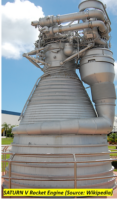
Actual Bell shaped geometry of the engine nozzle
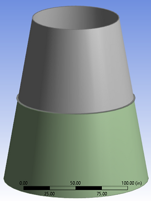
Approximate conical nozzle with 200 nuts and bolts
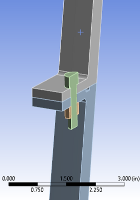
Half a bolt geometry considered for analysis by invoking symmetry features
DISCRETIZATION:
Hex Dominant mesh was used. Bolt and nut were meshed finer than the flange considering the size of the geometry and amount of discontinuities in the geometry.
GOVERNING EQUATIONS:
1. Force equilibrium in X, Y and Z directions
2. 3D Hooke's law with bolt pretension and thermal loading
3. Relation between strain and displacement
Giving 15 equations and 15 unknowns at each node.

Meshing of the geometry using Hex dominant elements
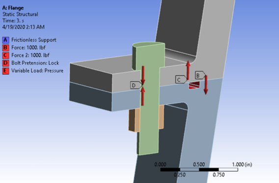
BOUNDARY CONDITIONS:
1. Exhaust Gas pressure and temperature (calculated using 1D gas dynamics) on exposed surface
2. Bolt Pretension on the bolt
3. Loads due to regeneration channels pulling the flanges apart
4. Frictionless fixed support at the top of the nozzle
5. Frictionless tangential surfaces of the geometry to ensure symmetry condition

SOLUTION:
The problem was executed in three steps:
Step 1: Application of bolt pretension
Step 2: Application of load due to regeneration channels
Step 3: Application of pressure and temperature loads
RESULTS:
Deformation of the flange assembly:

Deformation of the flange due to bolt pre-tension

Deformation of the flange due to bolt pre-tension and channel loads

Deformation of the flange under all loading conditions
Von-Mises and Normal Stresses:
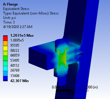

Von-Mises Stress in the geometry under full load condition
Normal stress on the flange surface
Gap Analysis:

Gap developed between the flanges under full loading
All the results were found to be within limits. Results were validated by sanity checks on boundary conditions and comparison with basic hand calculations on force reaction.